|
|
|||||||||||||||||||||||||||||||||||||||||||||||||||||||||||||||||||||||||||||||||||||||||||||||||||||||||||||||||||||||||||||||
| Home | News | Products | Service | Technology | Customer Area | Downloads | Links | Contact | |||||||||||||||||||||||||||||||||||||||||||||||||||||||||||||||||||||||||||||||||||||||||||||||||||||||||||||||||||||||||||||||
| > Technology > Software of the CME6005 | |||||||||||||||||||||||||||||||||||||||||||||||||||||||||||||||||||||||||||||||||||||||||||||||||||||||||||||||||||||||||||||||
All necessary constants, variables and function declarations are performed
before program start.
In the procedures init_NEC(), init_LCD() and init() all micro controller
specific and display initialisations as well as all variable definitions
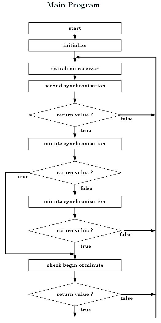
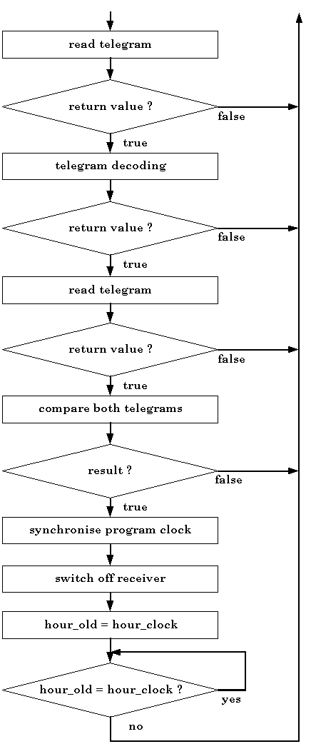
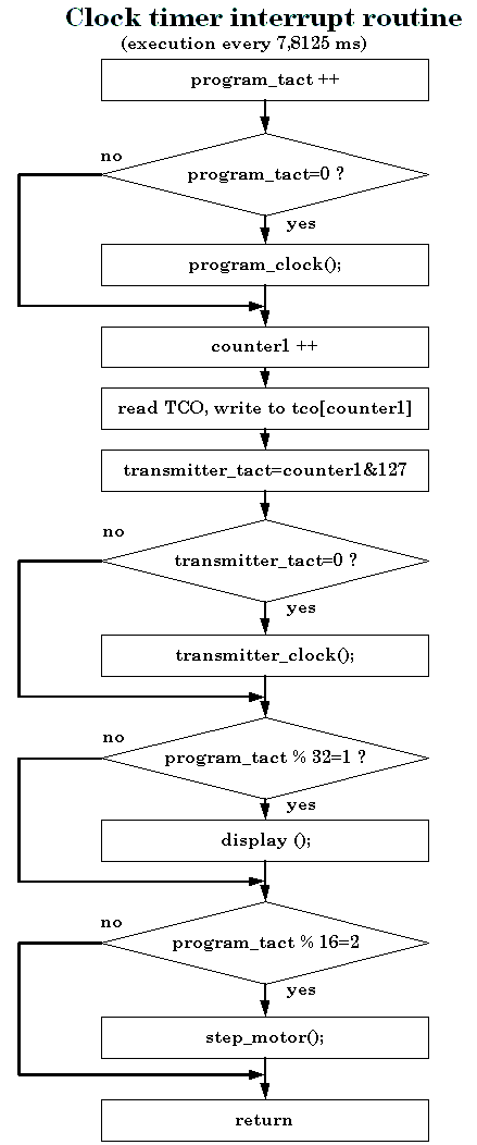
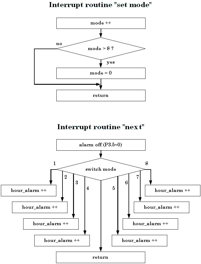
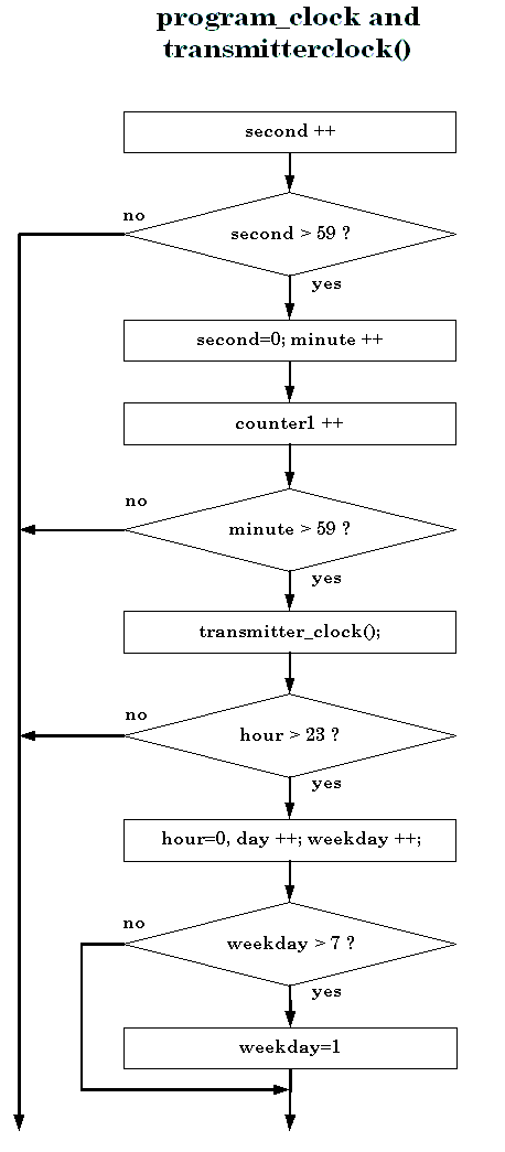
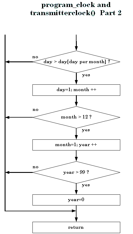
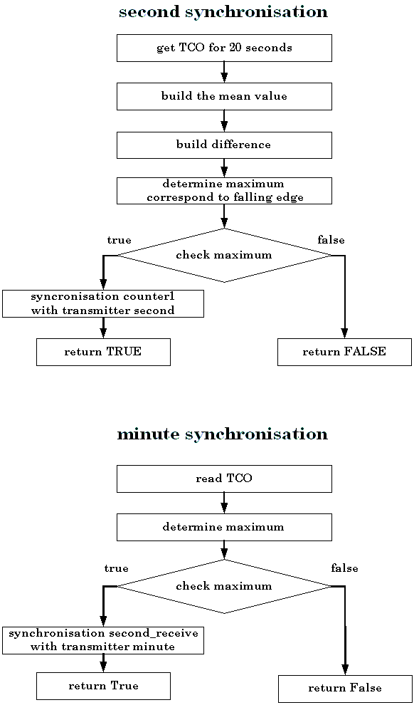
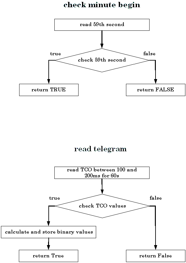
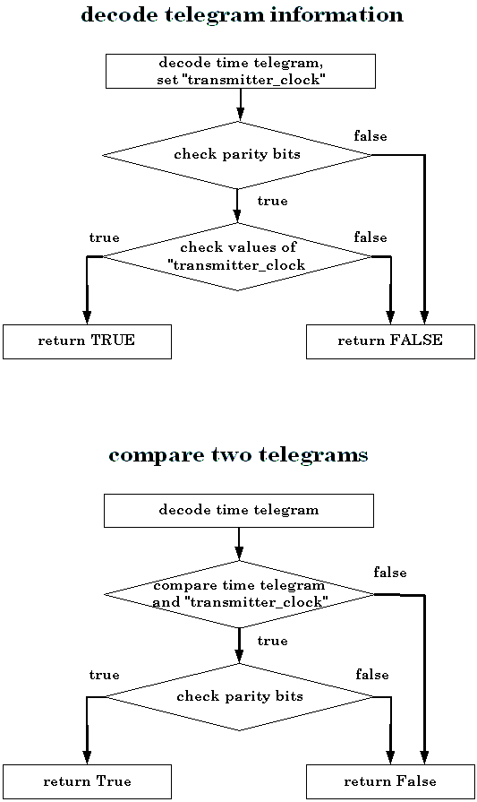
are made The clock timer interrupt routine is regular executed 128 times per second. In one run the counters "program_tact" (0 to 127) and "counter1" (0 to 255) are incremented by one. If "program_tact" is zero, the procedur "program_clock()" is run one time. A variable named "transmitter_tact" goes synchronous to "counter1 (from o to 127 and so long). If "transmitter_tact" goes synchronous to "counter1" (from 0 to 127 and so long). If "transmitter_tact" is equal zero, the procedure "transmitter_clock" is carried out. After that the TCO output from CME6005 is read and saved in array tco[counter1]. Four times per second the current values are written to the display, and eight times per second the procedure "stepmotor()" is carried out. The two external interrupts are necessary to set the program_clock, which is shown on the display (if reception is sufficient). By increment of variable "mode" (trough pushing button "Mode" and following call for "external interrupt 3") the time variable is set, and so displayed time variable is incremented by one through pushing button "Next". Both procedures program_clock() and transmitter_clock() almost are identical. Additional in program_clock() the procedure alarm() is called up every minute begin. In every run of the time counter procedures the second variables is incremented by one. If the second variable overflow 59, it is set to zero and the minute variables are incremented by one. This algorithm is worked out for all other time variables. IN "second_synchronisation()" TCO values for a time of 20 seconds are read (in a rate of 128 per second) and saved. A middle signal curve is built, and so a falling edge (in Japan rising edge) of the carrier can be detected relative certainly (greatest difference between two values). The difference must reach a minimum value to shut out accidents and make sure the following evaluation of the time code signal. After detected the second begin the transmitter clock is synchronised to the second of the transmitter. "minute_synchronization()" initiates reading TCO values of these parts of second, which marks the minute begin. After determining of best likeness of minute marker and read signal the minute begin of "transmitter_clock" is synchronised with the transmitter. In USA and Japan two reference seconds mark the minute begin. The minute begin is checked one time. The second (or two), which the minute begin marks, is read and also now a good likness must arise. Is the result negative, a new reception is started. In function "read_telegram()" it is read 5 (German, UK) or 21 (USA, Japan) TCO values from a range between 100 and 200ms ( German, UK), 200 and 500ms (USA) or 500 and 800ms (Japan) every second. The read values are summed, checked, converted to binary and stored into tco_decode[1...59]. All 5 (21) read values must be equal, because this range has no level change in the telegram send from the transmitter. Here has to be taken care for future additional services from the transmitter- provider, perhaps done in this area. If the values are not equal, a new reception is started. The decoding of binary values is performed in the function "decode()" in order to the specific code table. The parity bits are evaluated (Germany and GB only) and the decoded time data are checked by plausibility (a 28th hour, for example, is out of range). Are all verifications passed, the "transmitter_clock" is synchronised with the transmitter. To increase the immunity against reception errors by the function "comparison()"
a new telegram is received and compared with the current time and date
of the "transmitter_clock". If both data are equal, the return
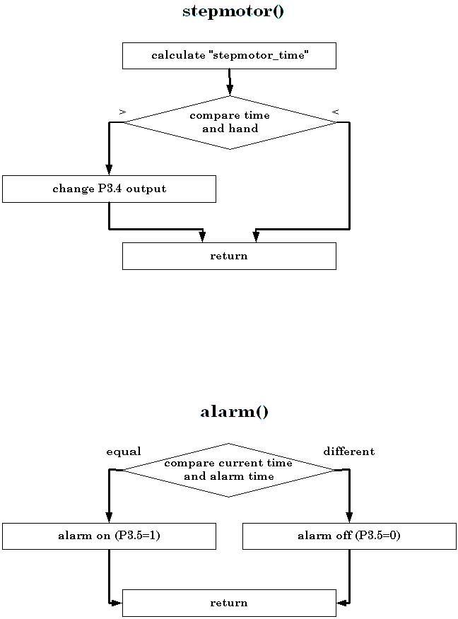
is done by TRUE and "program_clock" is synchronised with "transmitter_clock". In the procedure "alarm()" the alarm time is compared with the current time of "program_clock". Is the result positive and the level on port 2.0 low (Alarm on) there is an output of high level at port 3.5 for one minute (acoustic signal). A premature finish of the alarm signal is possible through pushing button "Next". The impulse output for controlling a stepping motor is realised by the
procedure "step_motor()" . The variable "stepmotor_time"
contains time in seconds starting at 00:00. "stepmotor_position"
contains the number of so far outputted impulses at port 3.4. Before start
of program the hands of an analogous clock must show 0:00:00. At begin
of every second on Port 3.4 the level is changed. The start level of P3.4
is L (o volts). If hand position and current time are different, following
solutions are possible: Putting on with 8x speed or putting back through
waiting. Waiting is only possible if difference between hand position
and current time is maximal three hours.
The control elements have the following meaning:
To output time data a LCD is used with 4 lines x 20 characters. The first line informs about in the third line shown the time data. Following kinds of output are possible: "Time", "Date", "Set alarm hour", "Set alarm minute", "Set hour", "Set minute", "Set day", "Set month", "Set year", and "Set weekday" (Germany and UK only). If the time telegram is received, in forth line shows up a "rec." And states the reception: "(I)" for initialisation of the receiver chip and microcontroller, "(S)" for second synchronisation, "(M)" for minute synchronisation, "(C)" for checking detected minute begin, "(R)" for reading and decoding of the time telegram an last "(C)" for comparison of current time of "transmitter_clock" with the time telegram of the next minute. Besides it is shown the time (the date during pushing the button "date") of "transmitter_clock". After successful reception "program_clock" is synchronised and this line is put out. Make Instructions (Compiler-/Linker-Options) Source code: brd.c (for example) Compiler: Linker: Conversion to NEC format
The software modules got following names:
|
|||||||||||||||||||||||||||||||||||||||||||||||||||||||||||||||||||||||||||||||||||||||||||||||||||||||||||||||||||||||||||||||


